
Single-pole or traditional light switches are effective for most applications but might be inconvenient if you have a large room. However, 3-way switches can enable you to control the bulb/fixture from more than one location, which is convenient. We will look at the 3-way lighting circuit to understand the wiring behind these switches and how it makes them work. Read on to learn more!
What Is a Three-Way Switch?
Also known as a 3-pole switch, a 3-way switch features three terminals to carry circuit electricity. It is a typical arrangement found in large houses to enable you to control one light fixture from different locations.
For instance, if you have a large living room, you can install one switch at the main entrance and the other at the end of the stairway.
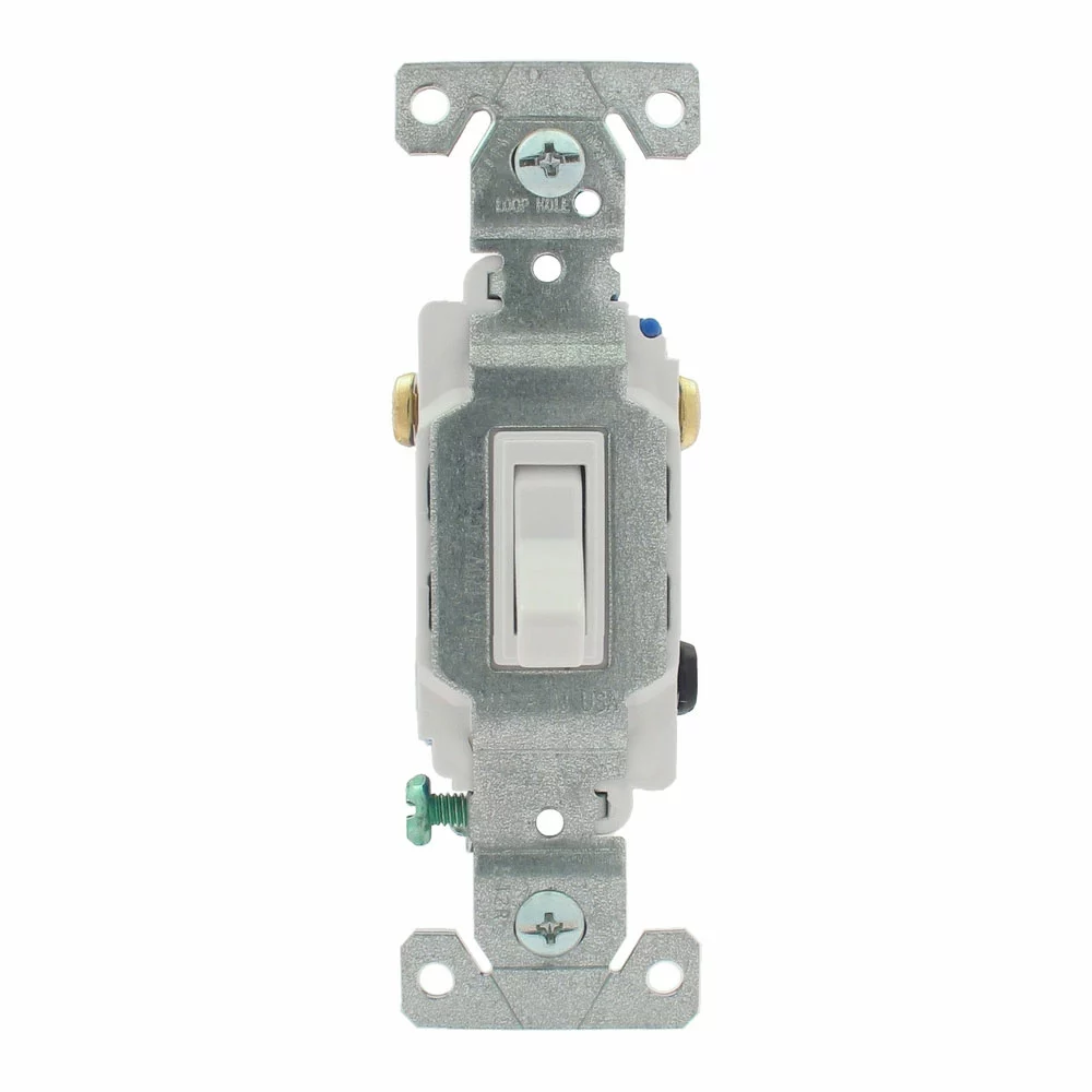
A three-way lighting switch
Or you can fit one switch close to the bedroom door and the other next to your bed. This multiway switching enables you to turn the central light fixture on when you enter the door, then turn it off when you get in bed.
Individual 3-way switch types resemble single-pole switches. But they do not have the on/off labels. They complete or discontinue the circuit based on the other switch’s position, so labeling them won’t make sense.
Three-way switch electrical circuits can also work with dimmer switches, so long as it supports 3-way switching.
3-Way Circuit Diagram
Three-way circuit diagrams can be in any of the following configurations.
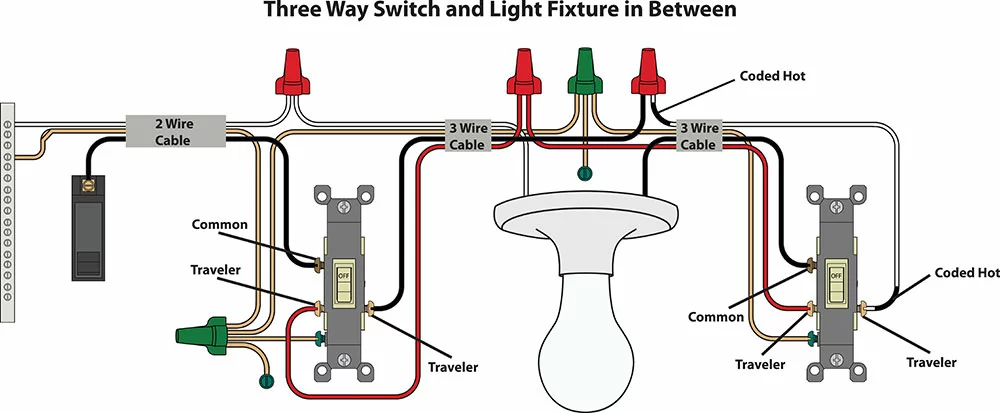
3-way switch wiring with the light fixture in between
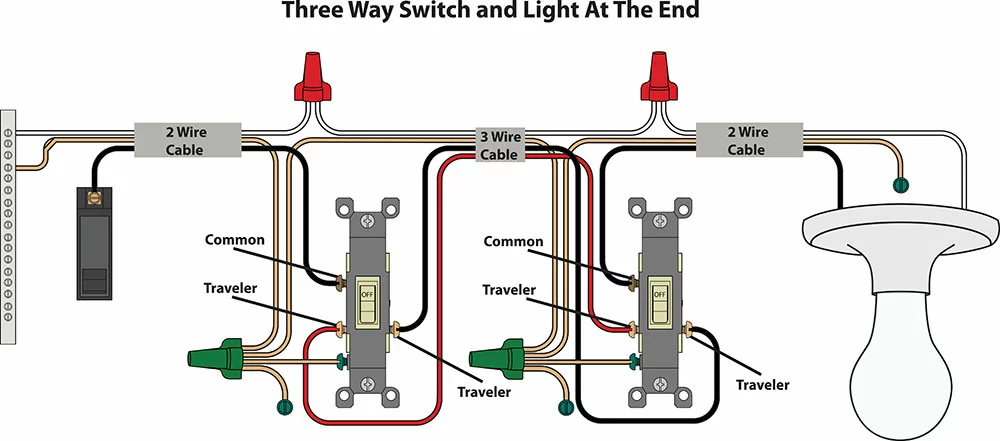
3-way switch wiring with the light fixture at the end
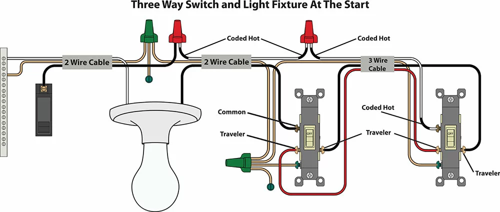
The 3-way switch wiring with the light fixture at the start
Although the position of the components differs, all circuits have the same components.
Types of Wires Used in Standard 3-Way Switch Circuits
Most standard 3-way lighting circuits use 14/2 and 14/3 cables. The first number (14) refers to the wire gauge, while the second digit indicates the number of conductors in the cable (two or three). The gauge rating shows the wire’s thickness and determines how much current it can carry. For instance, a 14-gauge wire has a 15-amp rating, while a 12-gauge wire has a 20-amp rating.
Parts of a 3-Way Switch Circuit Lighting System
The most complex part of a 3-way lighting circuit is the wiring. So without considering the light bulb, these are the parts of a 3-way switch circuit.
14/2 Wire
These cables feature two colored wire conductors (white and black wire) plus a third bare copper cable. The 14/2 wire connects the power source to the first switch box.
- Black Wire: The black or hot wire transmits power from the source to the first switch. It is also known as the line or common wire and always remains hot unless the circuit breaker is off.
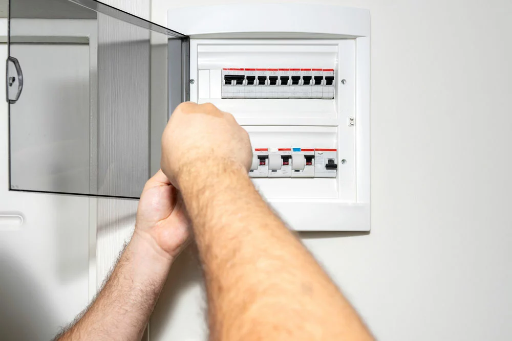
Circuit breakers in a circuit breaker panel
- White Wire: Also known as the neutral wire, the purpose of the white wire is to complete the circuit.
- Ground Wire: The ground wire can be bare or in a green sheath. It provides safety measures, such as draining current if a shorting occurs. So the ground wire does not transmit electricity when the 3-way circuit is operating correctly.
14/3 Wire
A 14/3 cable contains three colored wires (black, red, and white) plus a fourth bare copper wire. The cable connects the first switch box to the second switch box.
- Black Wire: This hot wire is a traveler wire because it transmits power from the first switch box to the second. The red wire is also a traveler. Current moves from one switch box to the other through them, but one at a time. The toggle switch configuration determines which wire acts as the traveler.
- Red Wire: The red wire serves the same purpose as its black counterpart. But only one can be hot at a time.
- White Wire: Like the 14/2 cable, this wire is neutral to complete the circuit.
- Ground Wire: Ground wires provide safety to the connection.
Neutral Wires
Neutral wires do not connect to toggle switches. They link together to form an uninterrupted return circuit to the power source. Usually, they link back to the bus bar terminal in the circuit breaker panel. You can connect these wires by twisting them together or using lever nut connectors.
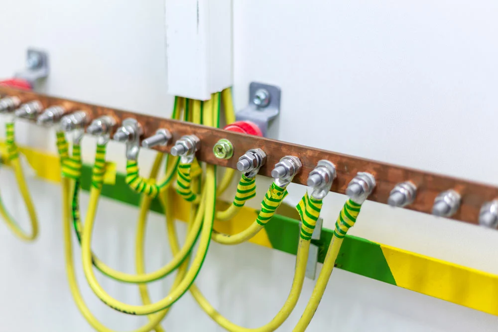
A bus bar terminal in a circuit breaker panel
Traveler Wires
The route of the traveler wires depends on the toggle switch position (up or down). If the first switch turns on the light, current will flow through one of these wires, say black. Turning off the light bulb using the second switch connects it to the other traveler wire (red). So if you turn on the light bulb again using the first switch, the red wire will be hot.
Screw Terminals
Standard 3-way switches feature four terminals, each with a colored screw. Every screw terminal in a 3-way circuit has a specific function, and the screw positioning is usually similar on all switches. They include the following.
- Black Terminal Screw: Also known as the common terminal, the black screw terminal attaches to the black wire in the 14/2 cable. It can have the COM label.
- Ground Terminal Screw: Each switch box has two ground wires (from the 14/2 and 14/3 cables). You should link these cables, then connect them to the green screw/earth terminal in each box.
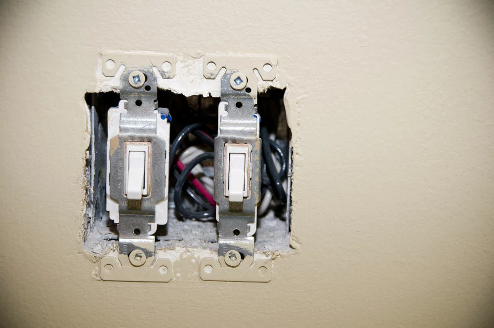
Light switches are installed on a switch box on a wall without the cover plate.
- Traveler Terminals (2): These brass terminal screws occur in pairs in each switch box to connect to the red and black hot wires. The red or black wire terminal connection order does not matter, but it should be the same in every box. For instance, if the first box has the red wire connected to the top traveler terminal and the black wire to the bottom terminal, the same order should apply to the second box.
2-Way Switches vs. 3-Way Switches
While a single-pole switch controls a light fixture from one point, 2-way and 3-way light switches enable you to switch lights on/off from more than one location. So what is the difference between the two?
First, it depends on the country. The terminology in the US is either single pole or three-way light switches. There are no 2-way switches. But in European countries, they refer to the 3-way light switch wiring as 2-way because they use two toggle switches in different locations to control the same light fixture.
So their standard 3-way switch setup features three switches to control a single light source from three locations. Therefore, the only difference is with the introduction of an intermediate switch.
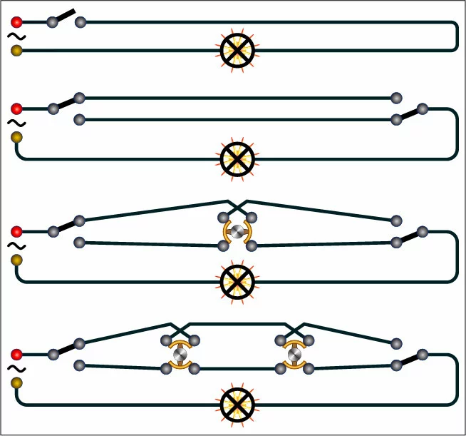
Lighting circuit diagrams. As per European standards, these diagrams refer to single-pole, 2-way, 3-way, and 4-way switch circuits. Note the intermediate switches in the 3- and 4-way switch circuits.
In a nutshell, a 3-way lighting circuit in the US refers to a connection with three-terminal switches for carrying electricity in the circuit. On the other hand, the same term refers to the number of light switches (three) in the circuit in European countries.
Wrap Up
In conclusion, 3-way lighting circuits might be challenging to install, but you can implement them as DIY projects using the guide above. You only need to ensure you use the correct wires and connect them, as shown above. That’s it for this article. If you have any questions or comments, reach out, and we’ll respond asap.