
We often see advertisers promoting their products on a flashing light visual display, grasping potential customers’ attention. You also might wonder how they generate such a pulsing and chasing effect. With an LED chaser circuit, the entire process starts and finishes through an integrated controller. Then, the cycle repeats, generating an effect as if an LED light chases the next LED in the set arrangement.
At OURPCB, we aim to put you on the right track toward understanding an LED chaser circuit. You will also learn how to create one yourself. So let’s get started!
What is the LED Chaser Circuit?
A light chaser serves as an LED driving circuit. It contains an arrangement of LEDs set in a certain pattern to provide a chasing light effect. For example, the LED chaser circuit creates the flashing light effect in a disco. Additionally, these popular circuits have common applications in signals, running-light rope, or advertising displays, producing pulsing light patterns.
More complex circuits usually contain microcontroller IC’s. In comparison, a simpler version requires the integration of ordinary IC’s, including the 555 and 4017. Many circuits utilize a CD4017 Johnson 10 stage decade counter. In effect, the electronic unit triggers the LEDs to switch on/off in a predetermined and repetitive cycle. As a result, this produces a visually appealing display with different light patterns around the LEDs.
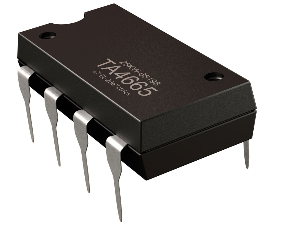
(A 555 IC timer)
We will take a look at how a reverse forward LED chaser operates. An integrated IC’s configuration provides a chasing mode. With diodes inserted at the IC’s output, the circuit generates a reverse and forward sequencing effect. Then, the diodes’ arrangement allows the IC’s output to illuminate each LED in a chasing light pattern.
It drives five outputs in a chasing pattern. Meanwhile, the other five outputs move in the opposite direction, reaching the LEDs. In effect, this generates the chasing pattern on a sequencer circuit.
How to Make the Best-led Chaser Circuit?
Components:
- 555 IC timer – 1x
- 4017 IC CD – 1x
- LEDs – 10x
- 470 Ohms resistor – 1x
- 1K Ohms resistor – 1x
- 47K Ohms resistor – 1x
- 1uF capacitor – 1x
- Breadboard – 1x
- Breadboard connectors – 18x
- 5-15V power supply – 1x
Follow these instructions to complete the circuit assembling process.
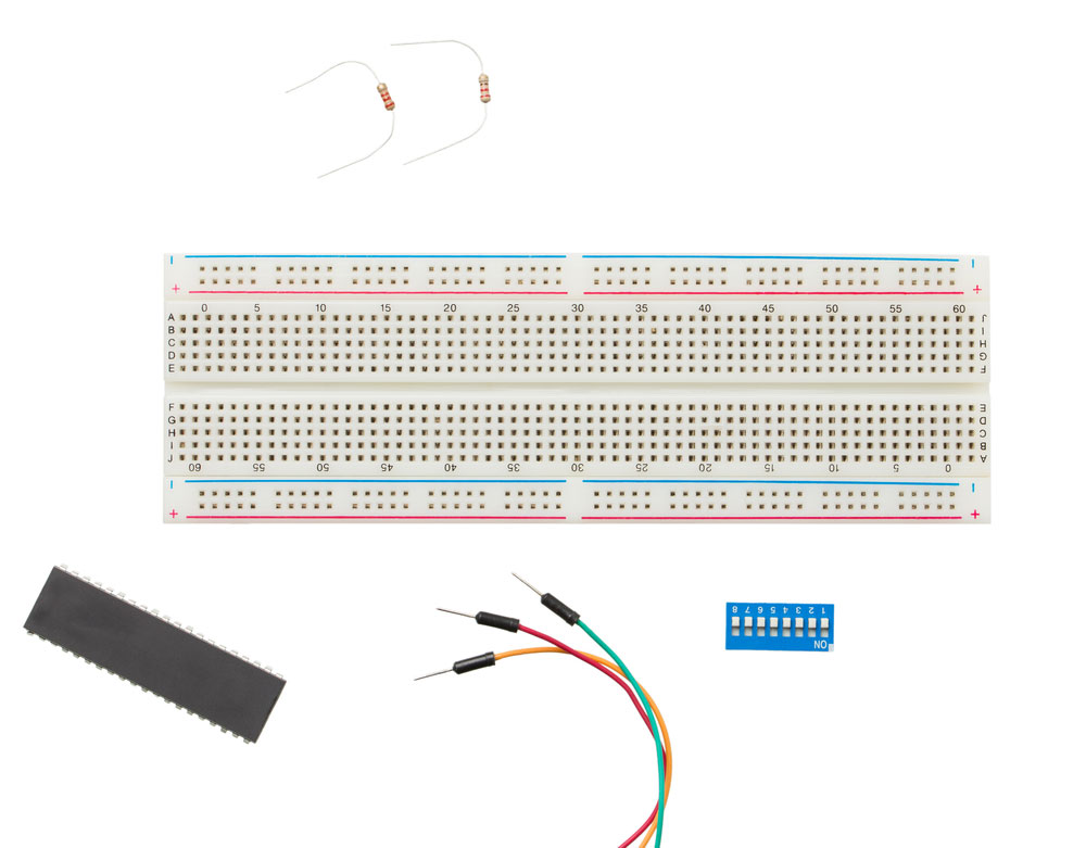
(All the components connect on a breadboard)
Step one:
First, integrate the 555 IC timer circuit onto the breadboard’s central divider. Ensure that the notch faces the left side so that pins 1,2,3,4 connect to four holes in the lower terminal strip. Then, pins 5,6,7,8 connect to four holes in the upper terminal strip. Next, grab two breadboard connectors. The first one will connect the 555 IC’s Pin 1 to the negative rail. Meanwhile, the second one connects the IC Timer’s Pin 8 to the positive rail.
Step two:
Position one connector between the 555 IC’s pin 2 lower terminal strip hole and pin 6 upper terminal strip hole. After that, connect the second connector to pin 4 and 8. Next, integrate the 1uF capacitor by connecting the negative end to IC’s pin 1. Then, join the capacitor’s positive end to IC’s pin 2.
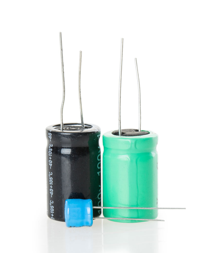
(The capacitor integrates on the breadboard)
Step three:
Add the 1K Ohms resistor by connecting one of its terminals to the IC’s pin seven and the other terminal to pin eight. Then, you will need to insert the 47K Ohms resistor so that it positions between the 555 IC timer’s 6th and 7th pins.
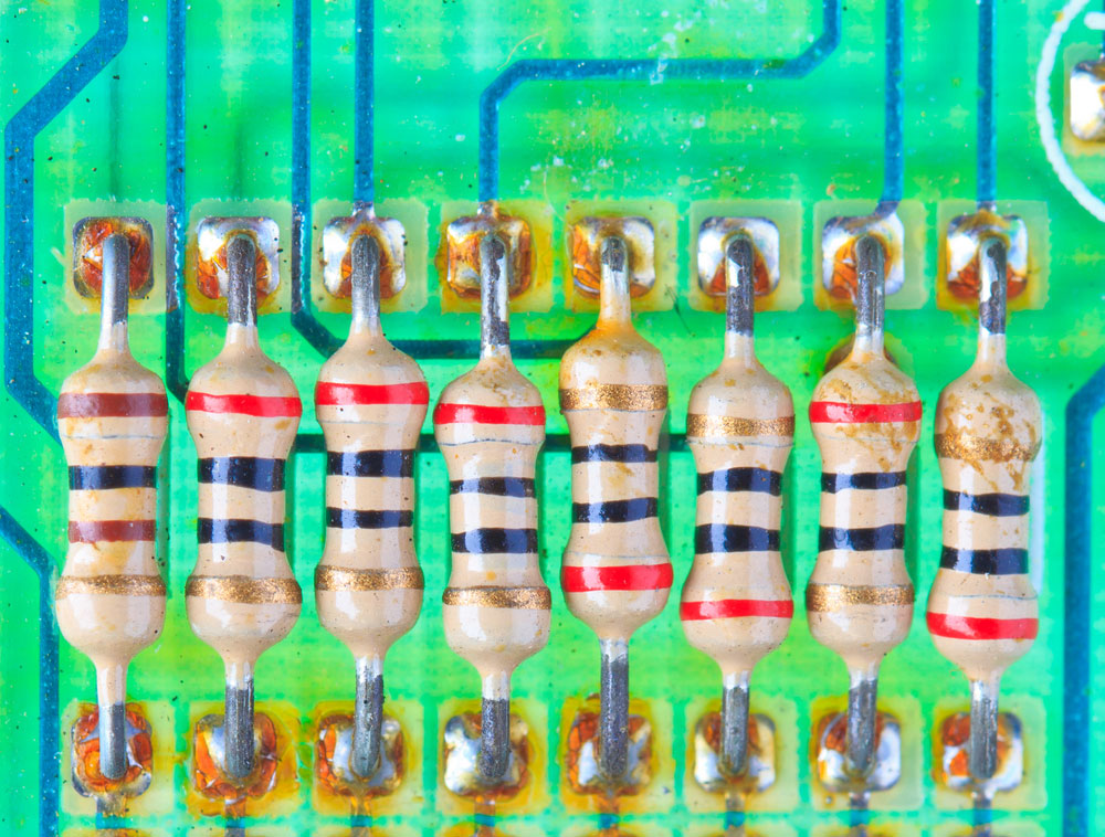
(Image showing a connected resistor)
Step four:
Insert the 4017 IC so that the notch faces the same direction as the 555 IC. Pins 1,2,3,4,5,6,7,8 should connect to eight holes in the lower terminal strip. Meanwhile, pins 9,10,11,12,13,14,15, 16 connect to eight holes in the upper terminal strip. Grab one connector and join the 4017 counter IC’s pin 16 to the breadboard’s positive rail. Then, you will need another connector to join the 4017’s pin 8 to the negative rail.
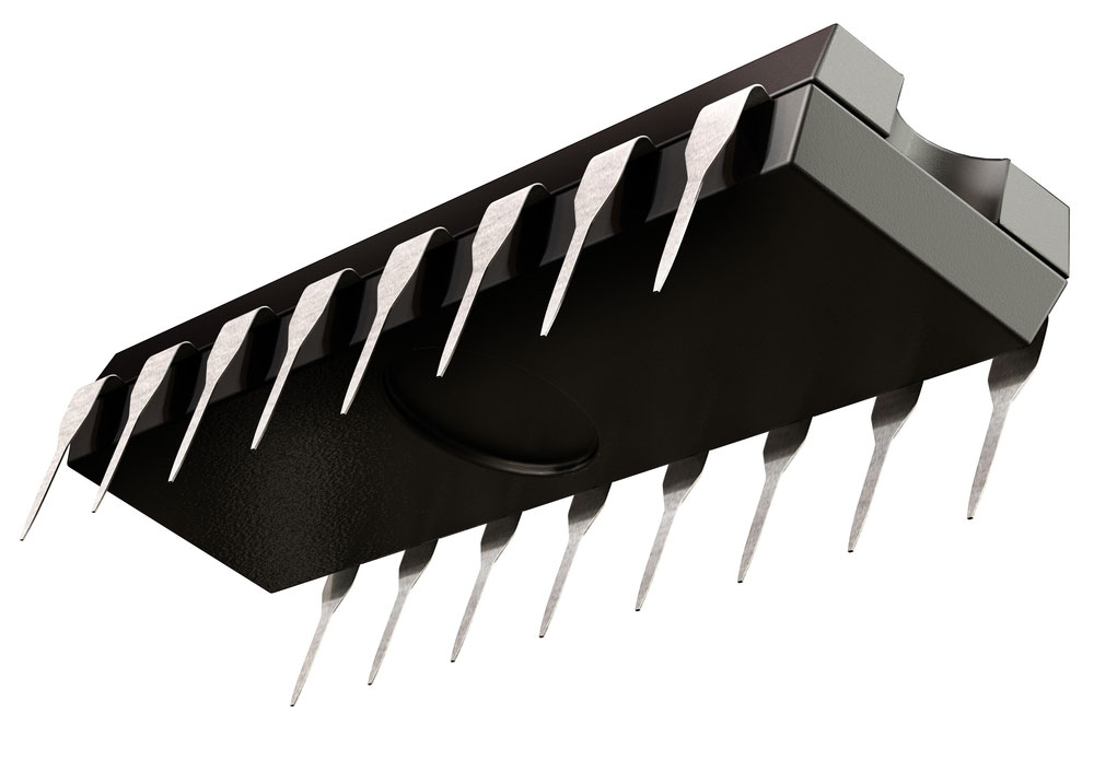
(A 16-pin 4017 integrated circuit)
Step five:
Next, use connectors to form a connection from the 4017 IC’s pin 8 lower terminal hole to pin 13 upper terminal holes. Then, make an additional connection from pin 8 to pin 15. Now, add the 470 Ohms resistor by connecting one end to the positive rail. The other resistor’s end must connect in parallel.
Step six:
Add ten LEDs to the breadboard. Place an LED’s negative terminal into a positive rail’s hole and the other end into the terminal strip’s hole. Use connectors to connect the 4017 IC’s pin 3 to the first LED. Connect pin 2 to the second LED, pin 4 to the third LED, and pin 7 to the fourth LED. Next, connect pin 10 to the fifth LED, pin 1 to the sixth LED, and pin 5 to the seventh LED. Lastly, join pin 6 to the eighth LED, pin nine to the ninth LED, and pin 11 to the tenth LED.
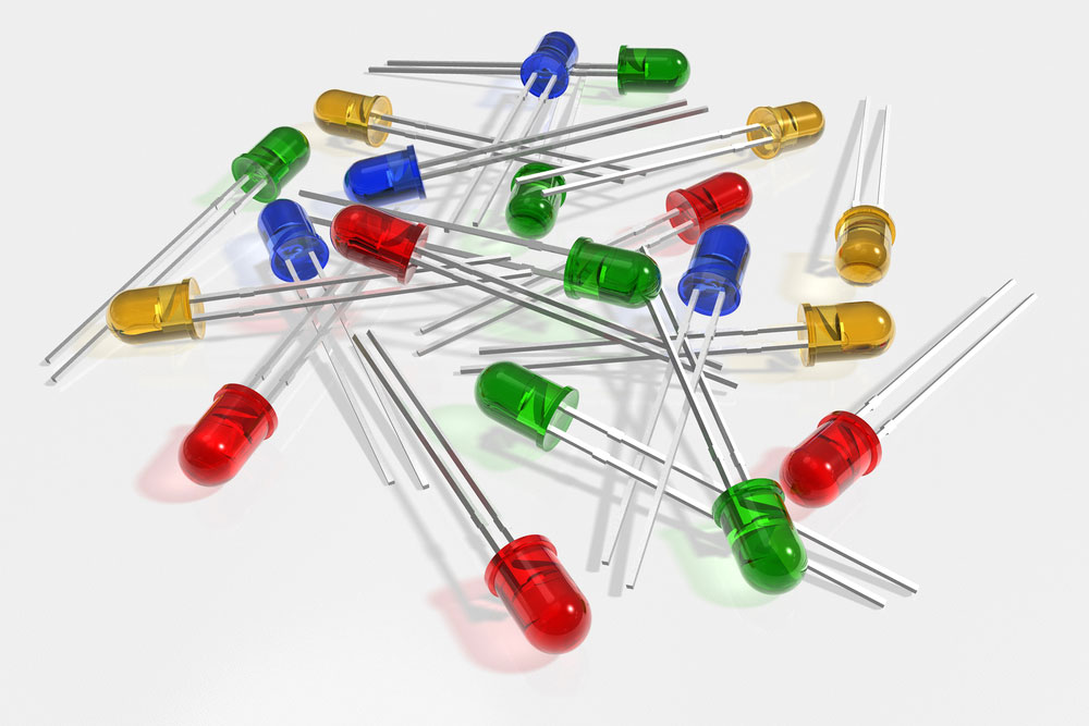
(Each LED will connect to a specific pin)
Step seven:
Lastly, hook up the power supply’s positive and negative ends to the breadboard’s rails, respectively.
Working principle:
Here, we will take a look at the LED chaser circuit action. The 555 IC timer operates in the astable state mode with a clock oscillator. It means that an LED will repeatedly flicker if it’s wired between the circuit’s ground and 555 IC’s output. When that happens, it triggers the output signal to alternate from high and low constantly.
After that occurs, the output transmits to the 4017 IC’s clock input pin. Each LED forms a connection with all of the 4017 IC’s ten pins. In effect, this triggers a looping cycle, where each LED turns on one by one in a pattern. First, the output pin #1 configures to on/high while the rest remain inactive. Once the 4017 IC’s clock input identifies a voltage boost, it switches the active output off. In turn, the next output switches into an active state. The transition from one output to the next progresses until it reaches the final LED. After that occurs, the first LED reverts to its default state. As a result, the swapping of output repeats the entire process.
Frequently Asked Questions About LED Follower Circuits
How can I force a five-second delay in a LED Follower Circuit?
You will need to integrate an astable and a monostable circuit. To achieve the five-second delay, you must reset the astable mode, which generates clock pulses.
Can you create an LED Follower Circuit without the IC microcontroller?
Yes. You will need to add a different component, like a transistor, to the circuit.
Can you adjust the LEDs chasing speed?
It can easily adjust the speed with an integrated potentiometer in place of the Ohm resistors.
Conclusion:
To conclude, an LED chaser circuit provides a chasing effect for each LED, making it an attractive display. Typically, a basic circuit utilizes a 555 IC and 1407 IC controller to produce a pulsing light effect. Meanwhile, a complex circuit will often incorporate a microcontroller. It controls the LED light’s switch timing and cycle. When an output switches on, the connected LED will illuminate. That process repeats to the next LED until it reaches the end. Then, the cycle repeats, demonstrating the chaser circuit’s capabilities. Overall, the so-called chaser circuit is a popular type of circuit with applications for advertising displays.
Do you have any questions regarding an LED chaser circuit? Feel free to contact us!