
You have probably come across LEDs (Light-Emitting Diodes) of varying brightness intensity. This feature is unique to LEDs. The main upside of using a LED is that you can easily change its brightness intensity. You can choose to make it brighter or dimmer depending on your preferences. You can also dim a bunch of LEDs that are in the same circuit. Nonetheless, you must primarily understand how a led dimmer circuit operates.
If you would like to know how this works, read on.
Led Dimmer Circuit Working Principles
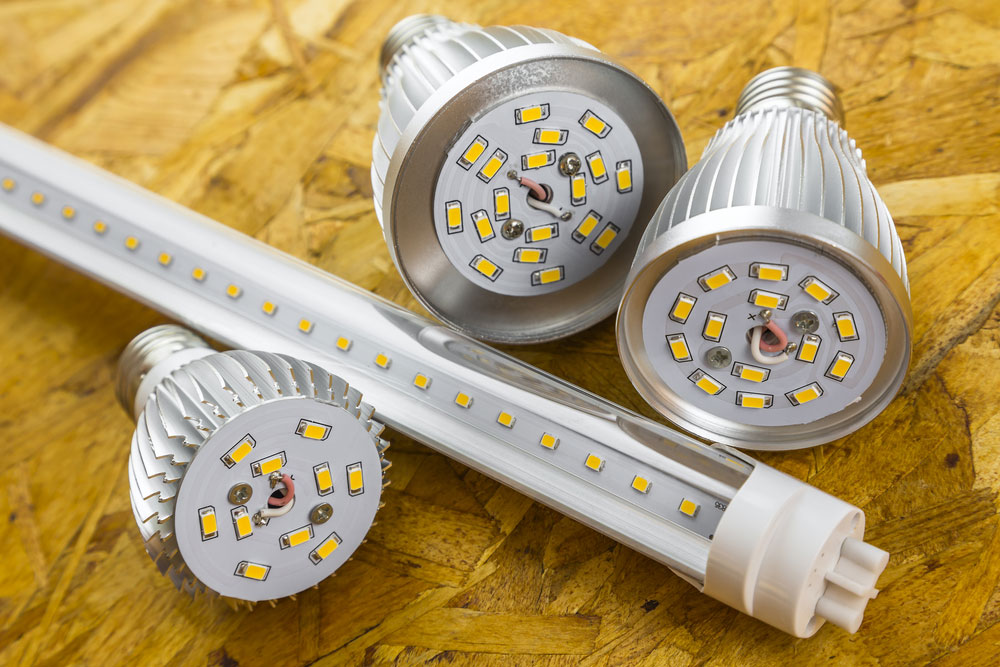
Figure 1: A LED Tube and bulbs
The fundamental LED dimmer circuit working principle is that LEDs are current-driven devices. It implies that their brightness intensity depends on the current that passes through them.
You only need a simple circuit to control the LED brightness level. For example, most simple LED dimmer circuits to consist of a resistor connected in series with the LED. It is one of the ways of dimming the LED.
You can also use a microcontroller such as Arduino or PICAXE. You can use this method when you want to dim a LED straightforwardly. A microcontroller such as Arduino does not require you to create a circuit from scratch.
What is the Purpose of the LED Dimmer Circuit?

Figure 2: Energy Saving Bulbs
There are several key purposes of a LED dimmer circuit. First, you can use the LED dimmer circuit to control the luminance of the light source. For example, if you want to have illumination that is not too bright, you can dim the LED to the desired level. It is especially applicable in amphitheaters and performance stages where dimming is necessary.
You can also use a LED dimmer circuit to control the energy consumption of the system. When you dim a LED, you are controlling the amount of current that it is using. As a result, you save energy.
7 simple LED dimming circuits
There are several types of LED dimming circuits. Among the key ones include the following:
- Simple LED Dimmer Circuits
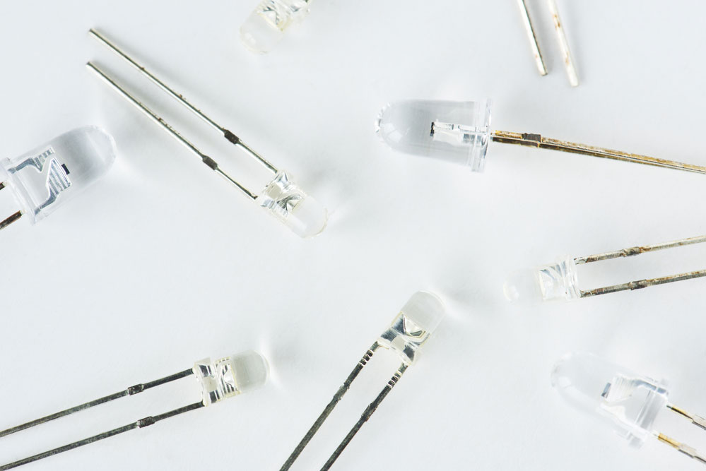
Figure 3: Simple LEDs
You can dim a LED by constructing a simple dimming circuit. All you need to have is a simple circuit comprising a power source, a dimmable LED lamp, and a potentiometer. In this circuit, you can monitor the brightness of the lamp by regulating the potentiometer. It is one of the simplest dimmer circuits. However, you can only use this method for a small LED load.
If you want better results, you can consider the pulse width modulation method (PWM). This method allows you to control several LEDs. It is a highly effective method that will enable you to dim the LEDs at high frequencies. With this method, you can also easily achieve a good duty cycle. It is the test of the period when the LED is on versus when it is off.
For best results and high frequency switching with the PWM method, you will require a 555 timer integrated circuit (IC). With this circuit, you can easily achieve a 12-volt DC Low-Voltage Dimmer.
- Dimmer controller for 1W LED or 3x1W RGB LED

Figure 4: Colored LEDs on a Circuit Board
To create this circuit, you primarily require a 0-10V control voltage input and a 1W LED bulb. You also need to connect the circuit to a 12V power supply. The other components include:
- 1.2 kohms 0.25W
- 33 ohms 5W
- One high current gain Darlington Transistor
As earlier stated, this setup allows you to monitor the control voltage within the 0-to-10-V system. When you set the lamp dimmer circuit at 0V, the LED will be off. On the other hand, when you change it to 10V, the LED will be completely on. To start dimming, you need to regulate the voltage between 1.3V to 9V. In this circuit, you do not necessarily need to have a heatsink to facilitate the working of the power transistor.
This circuit will experience the bulk of power loss on the resistor. You must also ensure that when creating this circuit, you use a high current gain transistor.
Also, this circuit is not highly efficient. It is because of operating the 1W LED bulb. You require roughly 4W. You will lose approximately 3W of this power in the lamp dimmer circuit. Therefore, while you can easily assemble this circuit, you will have to forego efficiency. It is because, with this dimming method, you will lose about 75% of the power. Also, note that you will lose this considerable power at any dimming setting.
- Adaptation for lower power supply voltage
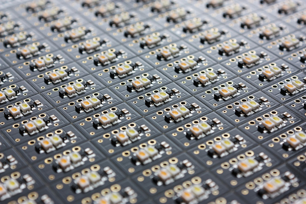
Figure 5: LEDs on PCB
For lower supply voltages, you can modify the components to include the following:
- Two 2.2 kohms 0.25W resistor
- One 15 ohms 2W
- One high current gain Darlington Transistor
With these components, you have now restricted the voltage loss to approximately 5V. Therefore, you can power this lamp dimmer circuit using a low voltage of at least 8V. Nonetheless, you must know that you need a heat sink if you choose to use the original 12V. You can even connect to a 15VDC power supply as long as you include a heat sink.
- Adaptation for 0-5V control voltage
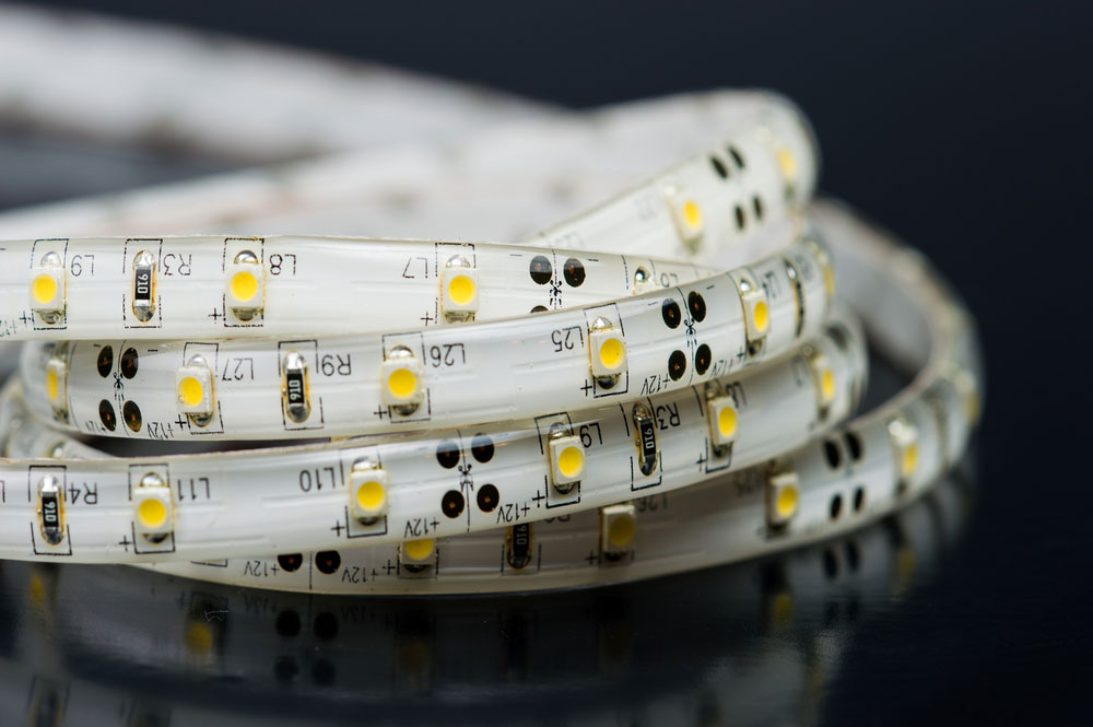
Figure 6: A LED Strip Light
You can minimize the voltage loss of the above-described circuit to facilitate the use of 0-5V voltage. For this, you require the following components:
- One 1.2 kohms 0.25W resistor
- One 15 ohms 2W resistor
- A high current gain Darlington Transistor
In this dimming method, you must have a heatsink for the power transistor. Also, you must maintain the control voltage to 5V to protect the LED from destruction. In this lamp dimmer circuit, the voltage range is between 0V to 5V. If you’re unsure how to maintain the control voltage to this value, consider including a 5.1V Zener diode. Also noteworthy is that this lamp dimmer circuit is efficient for PWM use.
- Dimmer for 1W LEDs driven with constant current source
Figure 7: Differently Colored Diode
You need to align the 1W LED bulb in a parallel arrangement with a constant current source. This setup’s principle is that when you want to dim a LED, the circuit will take some power. As a result, the LED will be dimmer than when it is using full power.
Given that the current source is constant, the LED plus the circuit will constantly be fed with the same power. Therefore, the more power that the lamp dimmer circuit takes, the dimmer the LED. To assemble this system, you require the following components:
- Two 2.2 kohms 0.25W
- One 4.7 ohms 2W resistor
- A transistor.
There are several things that you need to note when using this circuit. First, you must have a constant power source. If you cannot access constant power, you will not effectively create this system.
Also, you should know that this circuit is dissimilar to the 0-10V dimmers system. It means that when you set the current at 0V, the LED light bulbs will be fully on. On the other hand, when you change to 10V, the LED light bulbs will be off. You, therefore, achieve dimming at the voltages between 10V and 0V.
Lastly, you do not necessarily have to put the LEDs in parallel.

Figure 8: Arduino
If you would like to create a dimmer from scratch, a microcontroller is the best starting point. There are several kinds of microcontrollers, such as PICAXE or Arduino. Of the two, Arduino is the best for use with PWM.
There are several Arduino boards, and the most commonly used is the Arduino Uno. If you choose to use this particular board, you will find several pins for PWM output. You should connect your LED light bulb to the PWM-enabled pins. You should connect the Arduino to a potentiometer. Will then use the potentiometer to control the current that passes to the LED. It will determine the degree of brightness.
- Using a Dimmer with 12V MR16 LED Spotlights

Figure 9: LED Spotlights
You cannot use the above circuit to control 12V MR16 LED Spotlights. To power electronics of this kind, you need a compatible dimmer. While you will not harm the bulbs in this setting, you will also not achieve top-notch dimming. You can instead try using the other techniques mentioned above.
Conclusion
In a nutshell, the process of dimming a LED is straightforward. We have laid down some of the key types of circuits that you can use. Some are simple to assemble, while others will require you to secure sophisticated components. Depending on your need, you can easily select the method that perfectly suits you.
We not only offer advice on LED dimmer circuitry. We are also here to provide you with all the LED dimmer circuit components that you require. Contact us for any queries, and we will get back to you in the shortest possible time.