
Flashing LEDs produce an excellent display, especially when the holiday seasons roll around. Additionally, they serve as emergency devices when a user might be stranded. Not only that, but they also provide consistent brightness levels in an otherwise dark area. An LED flasher generally operates through a specific time control. In that case, each light-emitting diode will activate in succession on an electronic circuit. Of course, this configuration relies on some essential components to produce such an effect.
We wrote this guide to help you understand an LED flashing circuit’s capabilities. So let’s take a look!
1. What is a LED Flashing Circuit?

(An LED flashing circuit produces blinking patterns.)
An LED flasher circuit consists of LEDs that blink in a certain rhythm, producing a visually appealing effect. This electronic circuit mainly features resistors and capacitors, which aim to improve the blinking time. It generally serves many purposes in real-world applications, including Christmas decoration lights.
2. LED Flashing Circuits Examples
We provided five examples of LED flashing circuits with circuit diagrams:
Led flashing circuit using simple relay:
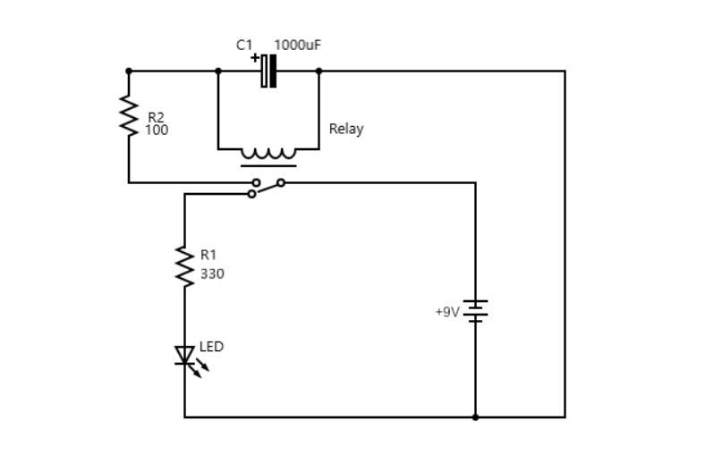
(LED flashing circuit with simple relay circuit diagram.)
The above circuit relies on a 9V battery, relay, onboard LED, polarized capacitor, and two resistors to produce flashing effects. Integrating a resistor and capacitor reduces the relay’s switching time; and otherwise, it will change too rapidly, making it difficult to see the LED blink.
The 9V battery will charge the capacitor via the R2 100k resistor. Afterward, the relay coil switches the relay into the opposite setting. In effect, the LED will blink. Also, the charged capacitor locks the relay into position. However, it can only power the relay’s electromagnet for a short period before becoming discharged.
Once the capacitor runs out of power, the relay sets into its original position, causing the LED to deactivate. Afterward, the cycle repeats.
Transistor for flashing led:

(Circuit diagram showing a flashing LED with two transistors.)
Now, we introduce a simple circuit featuring two NPN transistors that operate as a switch, causing both LEDs to blink sequentially. It also utilizes two capacitors for this effect. First, a voltage source distributes current to the circuit. Then, this current passes LED1, R1 resistor, and the Q1 transistor’s collector-emitter terminal.
Next, the current passes through LED2 and the R4 resistor. Then, it will fully charge the C2 capacitor. In particular, this whole process occurs shortly after the first LED flash. After a while, the base emitter’s VBE voltage level will reach below 0.7V, causing LED1 to turn off when the Q1 NPN transistor deactivates.
LED2’s brightness level will intensify after the Q2 NPN transistor activates. While LED2’s brightness level increases, the C1 capacitor will begin charging until Q2 deactivates. Finally, LED2 turns off when the VBE reaches less than 0.7V.
Blinking an led with an inverter:

(LED flashing circuit diagram with an inverter.)
This primary flasher circuit generally relies on a few components to achieve blinking. It features a Schmitt trigger inverter, resistors, a polarized capacitor, an LED, and a 9V battery.
A 10k resistor forms a connection with the inverter’s output and input. Therefore, a high input voltage will result in a low output voltage. However, the input voltage stays low since it connects to the output. And this will result in high production. In turn, this produces a high input. As a result, the entire process switches from high and low.
A polarized capacitor also connects to the inverter’s input, slowing the switching process. Another resistor, R1, controls the current level, which charges the capacitor. Therefore, both resistor’s and capacitor’s sizes will determine how rapidly the LED blinks.
Blinking led circuit with microcontroller:

(Circuit diagram with the ATMEGA8535 microcontroller.)
A microcontroller provides ease of usability and efficiency regarding blinking LEDs. In the circuit diagram, eight LEDs and resistors connect to an ATMEGA8535 microcontroller, providing blinking patterns. D0 to D7 defines each LED starting from right to left. PORT. A serves as the output that supplies 5V to each LED, which causes them to flash.
Very simple led flashing with sound:

(Simple LED flashing circuit diagram with sound.)
This primary circuit, as shown above, utilizes an 8 Ohms speaker that generates sound in succession with the LED’s flashing pattern. It relies on a 4.5V battery as the primary power source, distributed to the FRL 4403 LED.
3. Applications of led flashing circuits

(Strobe lights feature an LED flashing circuit.)
The following applications utilize LED circuits:
- Strobe lights and SoS signal circuits
- Car light indicators
- Wiper motors
- Turning indicator circuits for vehicles and cycles
- Counter circuits
Summary
Overall, LED flashing circuits provide excellent benefits for any user. Because of their ability to blink promptly, these serve as practical applications. Additionally, an LED flasher helps to improve your holiday decorations. In that case, it provides a light effect that will grab passerby’s attention, allowing them to appreciate the display even more. You can also create and utilize a basic flasher yourself for any project, which will provide a rewarding experience!
Do you have any questions regarding a flashing LED circuit? Feel free to contact us!