
LEDs have become available and inexpensive stock-order light sources over the years. Plus, you can use LEDs for various beautiful light projects. One such project is the LED scanner.
LED scanners can deliver intense electronic dimming light that enhances your lighting setup while giving you eye-catching effects. Also, you can use it for built-in automated programs that enhance the anti-theft system. Hence, it can protect against the loss of credit card details.
However, the more power an LED scanner has, the more expensive it gets.
So, in this article, we’ll focus on building simple LED scanners without mounting many components or making printed circuit boards. You’ll also be seeing the percentage breakdown and accuracy of measurements. Also, this circuit uses the back-and-forth effect to give the chaser effect.
Are you ready? Then, let’s begin.
How to Build an Easy LED Scanner Circuit
This section will teach us how to make an LED scanner using a MOSFET, Arduino, and sixteen LEDs. So, before we begin, here’s a quick look at the schematics of this circuit:

Schematics 1
Source: Wikimedia Commons

Arduino Schematics
Source: Wikimedia Commons

TLC5940 Schematics
Source: Wikimedia Commons
Steps
Here are the steps for building this circuit:
Step 1: Gather your Materials, Product Dimensions, and Components
- 10W LED lights (16)
- 750 Ohm 1W resistor (1)
- TLCS940 Breakout Board (1)
- Heat sinks (16)
- ½” X 1 ½” 6ft angle aluminum (1)
- 12-volt power supply (1)
- LED scanner stand (1)
- Arduino pro mini board (1)
- 2N3904 transistor (1)
- 22 gauge wire for connections (1)
- 18 gauge wire for power leads (1)
- Screws and nuts
- Soldering iron
- Soldering wire
- 8-32 tap
- 4-40 tap
- Drill and drill bits
- Heat shrink tubing
- Tie wraps
Step 2: Build Your LED Modules
So, before kicking off, you must know that each LED module must have a constant current regulator to work correctly. First, gather your heat sinks and drill 4-40 holes for mounting the LED.
Next, take your aluminum piece and drill 8-32 holes. Next, attach the heat sink with your 4-40 screws. Also, bend the two leads of emitter elements for the heat sink. Then, keep the middle lead straight. Next, take your transistor and turn the correct information at a 90-degree angle to meet the basic measurements.
That’s not all.
Next, spread the other legs of the transistor to about 45 degrees apart and create half loops on the end of the leads and avoid absolute errors.

Transistor Lead Half-Loop
Source: Wikimedia Commons
Also, attach these half-loops to the leads of the heat sink and connect one 75 Ohm resistor to the information at the right end of the heat sink. Also, take the 90-degree lead and form a loop to work as the ground connection. Again, ensure that you’re working with precise measurement and range to avoid error bars. If possible, confirm and check the measurement accuracy and sensor measurements.
Now, it’s time to connect to your LED module. So, take the center lead of the heat sink to the negative information (cathode) of the LED module:
Now repeat the process for the remaining 15 LED modules.
Step 3: Connect your Arduino and Breakout Board
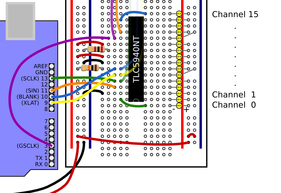
Arduino and Breakout Board Connection
Source: Wikimedia Commons
For power, ensure a connection between the grounds of both boards. Plus, you can find an unregulated positive input voltage pin (RAW). Then, you can connect it to the breakout board’s VCC pin to avoid absolute error rates.
The breakout and Arduino boards feature a +5V regulator that handles up to 17 volts. Also, before mounting your circuits, program your Arduino first.
So, with this code, we’ll assign the fade function to one LED and wait 40msec before switching to the next LED. Each LED will have a 470msec fade time.
LED
Once the circuit finishes the scan in one direction, it’ll scan in the other direction. Plus, it’s easy to change the values of the LED or set it to check in only one guide.
Thus, this code will set the fade value from 0 to 4095. In other words, it puts it from complete on to full-off.
Code:
#include “Tlc5940.h”
#include “tlc_fades.h”
TLC_CHANNEL_TYPE channel;
void setup()
{
Tlc.init(4095);
}
uint16_t duration = 470;
int maxValue = 4095;
int fadeTime = 40;
uint32_t startMillis;
uint32_t endMillis;
void loop()
{
if (tlc_fadeBufferSize == 0)
{
// no fades are currently running
start mills = millis();
endmills = start mills + duration;
for (int i=0; i<16; ++i) {
tlc_addFade(15-i, 0, maxValue, startMillis+fadeTime*i, endMillis+fadeTime*i);
}
}
tlc_updateFades();
delay(5);
if (tlc_fadeBufferSize == 0)
{
// no fades are currently running
start mills = millis();
endmills = start mills + duration;
for (int i=0; i<16; ++i) {
tlc_addFade(i, 0, maxValue, startMillis+fadeTime*i, endMillis+fadeTime*i);
}
}
tlc_updateFades();
delay(5);
}
Step 4: Mount your LED Modules
Now, it’s time to attach the LED modules to the aluminum angle. So, measure sixteen holes with even spaces and connect the LED modules. Also, make a few more holes to attach the Arduino and Breakout board to the aluminum angle.

Aluminum Angle
Source: Wikimedia Commons
Additionally, use 8-32 screws to secure the heat sinks to the aluminum. Start connecting your modules to the positive active unit and ground wires when everything is set. We also divided the sixteen LEDs into four sets. So, ensure you click the four sets at one junction with your 18 gauge base height wire.
Next, connect all four power wires and the circuit board’s power wire to your 16 gauge wire, then connect it to your 12v power supply.
Once you’re through with the power wires, connect the control line of each LED module and click the transistor’s collector pin to the breakout board. Plus, you can use tie wraps to keep your connections neat.
After the connections, examine what you’ve done and ensure you have the correct links. You could damage your LEDs if you make the wrong connections.
If you’re okay with your work, turn on your compact LED scanner circuit and watch it glow.
Wrapping Up
Before we round up this article, it’s ideal to know that an LED scanner needs a current regulator to work correctly. So, for this circuit, you can use the 2N3904 NPN transistor as the significant component. Also, you may notice a voltage drop on the base-emitter junction when it’s forward-biased and a height above.
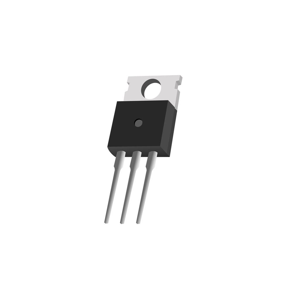
NPN Transistor
This voltage also works on the current sensing resistor. Plus, this is where the current from the LED flows to the ground.
Additionally, the current regulator handles three versions of this LED circuit: firstly, the constant supply of LED current without control. Second, direct supervision from the Arduino board, and lastly, power from the SparkFun breakout board.
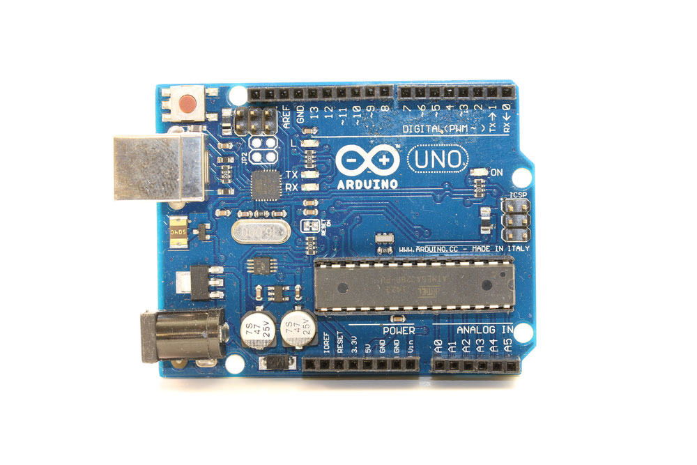
Arduino Board
That wraps up this article. If you need more information, don’t hesitate to contact us. We’re always happy to help.