
Many people think building a led strobe circuit is difficult because flashing effects form through an intricate xenon flash tube. However, with a proper driving circuit, making a light strobe is easy. For your light project, you can find the materials at any DIY store.
There’s certainly nothing more intriguing than seeing an electronic circuit emit LED on and off. If you’re interested in learning about strobe lights and how they work, you are in the right place. Here, you will learn how to build a strobe light using a circuit board to generate the appropriate flash output.
1.What is a LED Strobe Circuit?
A LED strobe light is simply light with bright pulses. It produces a very intense and regular flash of light. Strobe lights are also known as mono lights (single-pulse strobe lights). The strobe effects emit from a stroboscopic device. An excellent example of strobe light is the blue and red overhead lights on a police vehicle.
Halogen lights, LED lights, and xenon flash lamps are all common light sources for strobe kits. Presently, they are a significant aspect of flashlights. Strobe lights are not only for illumination but are also helpful as a self-defense weapon. Plus, they are also the regular blinking device in party halls and clubs.
Strobes have a short recycle time and a full flash output of anywhere from 100 to 1,000 watts. Above all, stroboscopic effects certainly emit from special lighting devices that produce a brief flash LED strobe light. You can also find them in medical and commercial-industrial applications.

(led strobe light on a police car)
2. Difference Between A Flash and Strobe
Electronic enthusiasts often confuse the term strobe flash and strobe light. The strobe flash of light is indeed as eye-catching as the strobe flash. Therefore, they are functional in many areas as entertainment devices. However, one significant difference between flashing and strobing is the flash energy.
Although a strobe light has a flashing light, the flash mode is certainly different. A strobe flash is also brighter and creates tremendously short bursts of light. Meanwhile, a strobe light has a pulse-switching light.
Unlike flashing, the strobe light double flash pattern is (2 x 20ms flashes per second) optimized to create sharp blinking flashes of light. Like strobes, flash undoubtedly has a short flash duration, but they have an extended recycle time and less precise color.
3. How to make a strobe light using 555?
These DIY projects certainly show a schematic diagram on building a LED Strobe Control Circuit using 555 Timer IC, flashing 2 LEDs with an external circuit, as well as the circuit design.
- Hardware
This hardware is indeed a compulsory item for the LED strobe light project.
| Hardware Required | Quantity |
| 9v battery pack or DC power supply voltage | 1 |
| IC 555 Timer | 1 |
| 12v feed wires | 1 |
| Breadboard | 1 |
| Variable resistor 100KΩ (1M ohm) | 1 |
| Ceramic capacitor (0.1µF, 0.01µF) | 1 |
| High power white LED of the T-1 ¾ size | 1 |
| Resistor 10KΩ, 10Ω/1w (10k ohm) | 1 |
LED strobe circuit components
Source: Pixabay
- How to connect
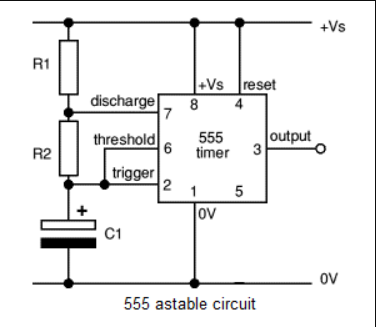
The building of the ground circuit starts with IC 555 Timer and timing elements resistor RV1 & R1 and also the capacitor C1. To get a dark-activated light circuit, you particularly need a 9v battery as the power source.
But if you have an external power supply instead, adjust it to get a 9 volt supply. Additionally, you’ll require feed wire interfaces to join the separate resistor and capacitor to the 555 timer chip. That said,
- To begin with, connect pins 8 & 4 to the positive terminal of the 9v battery.
- Secondly, connect Pin 1 to negative supply (GND).
- Next, fix Pin 5 with negative supply through Capacitor 2.
- Afterward, include Variable resistor RV1, R1 between Pin 6 & 7.
- Connect 0.1uF threshold Capacitor between trigger pulse Pin 2 & GND.
- Connect 0.01uF Capacitor between Pin 5 & negative supply (GND).
- Add 10k Resistor between the battery holders and Pin 7.
- Finally, Output Pin 3 from IC 555 Timer also goes with a High Power LED capacitor through resistor R2.
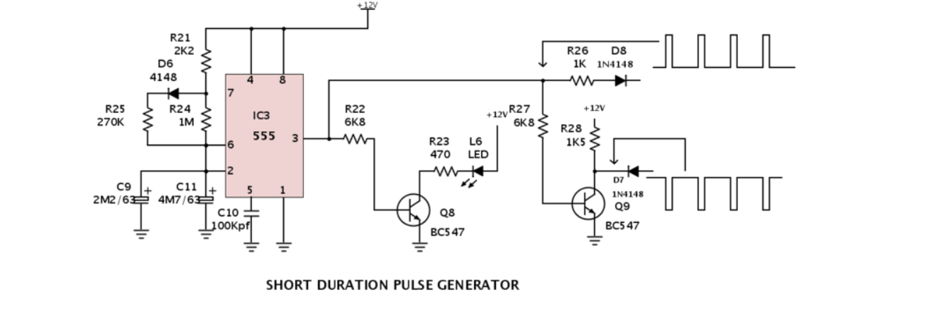
LED strobe light circuit IC 555 Timer
Source: https://commons.m.wikimedia.org/wiki/File:Short_Duration_Pulse_Generator.png
Working
In the light circuit, IC 555 Timer works as an astable multivibrator. By this we mean, it has no stable state. The LED driver circuit creates a continuous square pulse output. Additionally, the waves make the LED On and Off. Besides, the duration of the flash signal depends upon the duty cycle drive of the square wave. You can also control the blinking speed of the led strobe circuit by turning the potentiometer knob. Moreover, the 1 watt LED driver has dual terminals: Cathode (-) and Anode (+). However, if you prefer to run the entire circuit continuously, use a 1 watt LED alongside a LED heat sink. Therefore, the value of RV1 value has a maximum current close to the 100mA pulse rating.
- Circuit design
You can indeed understand the complete circuit diagram through these pointers.
- Gate pulses N1 and N2 are operated as simple oscillators. So they produce both alternate logic lo and alternate hi-output. These oscillators are also clock pulses.
- The oscillator N1 clock signal links to the analog input of the IC 4017.
- The clock signals are usually converted to high logic pulses by IC 4017 through the flash output pins.
- From the circuit diagram, you’ll further notice that the cathode point of the custom LED array connects to the N2 output oscillator.
- The circuit details are truly interesting because it forces the LEDs to have an exact flash sequence at an adjustable pulse frequency. In other words, the constant voltage circuit makes the array of LEDs flash either “chase” or “run” simultaneously.
- The rate duty cycle is also among the essential basic components when building a fantastic application like the LED strobe circuit. The duty cycle you pick undoubtedly determines how long the LED will remain on rather than off. For example, if your duty cycle is 20%, it means the LED flash will stay in for 20% and off for 80%.
Flashing 2 LEDs
Again, you can modify the working above so that the LEDs will flash alternately. Therefore, as one flashes off, the other flashes on in the cycle.
- Additional Components
- Red LED
- 1KΩ Resistor
- Circuit diagram
The blinking LED circuit with schematics and explanation of the flashing 2 LEDs is shown below.
Flashing 2 LED circuits creating double stroboscopic effects
Source: https://commons.wikimedia.org/wiki/File:A_555_circuit.png
Conclusion
The fun project of building a LED strobe circuit is undoubtedly easy when you have both a suitable driving circuit and an Arduino LED Flasher circuit board. Making your strobe DIY gives you the flexibility to adjust and alter the frequency of the pulses. Hence, you can make them extremely rapid with many light bursts or slow them down with a few flashes. When it comes to making a led strobe circuit yourself, there are numerous options available.